Driving Cabs
Second Generation DMUs
|
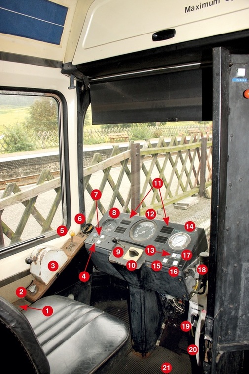
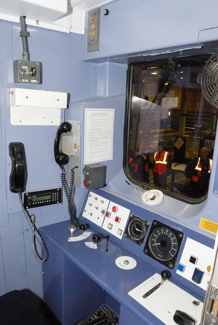
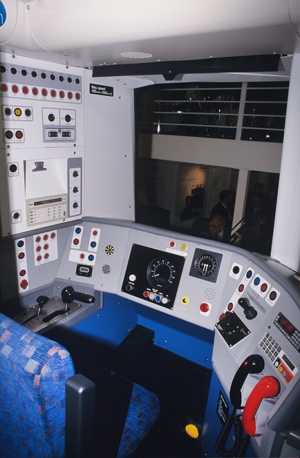
LEV1 driving cab controls. View shows the ‘A’ or master cab. 1: External light switches, side lights, internal light switches and master switch (left of drivers seat), 2: Windscreen wiper control valve, 3: Electro Pneumatic (EP) power and brake controller, 4: Left side rear door open/close buttons, 5: Air throttle, 6: Supplementary heater control switch, 7: Right side front door open/close buttons, 8: Spring brake reservoir pressure gauge (top) / Service brake reservoir pressure gauge (bottom), 9: Warning horn valve, 10: Master switch (forward/neutral/reverse), 11: Indicator lights (coolant, service brake, charge indicator, low air, door open, oil, spring brake, gearbox), 12: Speedometer, 13: Cab light on button, 14: Brake actuator pressure, 15: Cold start button, 16: Test/buzzer button, 17: Cab light off button, 18: Air brake controller, 19: DSD isolator switch, 20: Intercom telephone handset, 21: DSD pedal. MJC
|
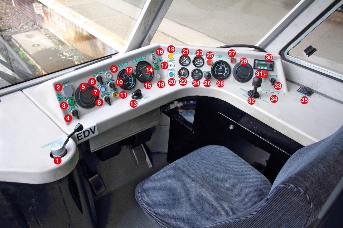
1: Pneumatic brake valve, 2: Door open button left side, 3: Door close left side, 4: Horn switch, 5: Cab air vent, 6: Windscreen wiper switch, 7: Saloon light switch, 8: Cab demist fan switch, 9: Screen wash button, 10: Headlight switch, 11: Saloon heat, 12: Flywheel RPM, 13: Engine speed control, 14: Door close right side, 15: Speedometer, 16: Door open right side, 17: Cab key socket, 18: Public address button, 19: Engine oil pressure light, 20: Take control, 21: Brake pressure, 22: Engine temperature, 23: Main air system pressure, 24: Running hours, 25: Ignition button, 26: Engine key, 27: Fire alarm, 28: Engine RPM, 29: Cab air vent, 30: Radio and communication system, 31: Emergency brake plunger, 32: Hydrostatic power/brake controller, 33: LPG switch, 34: LPG, 35: Cab heat control. JS
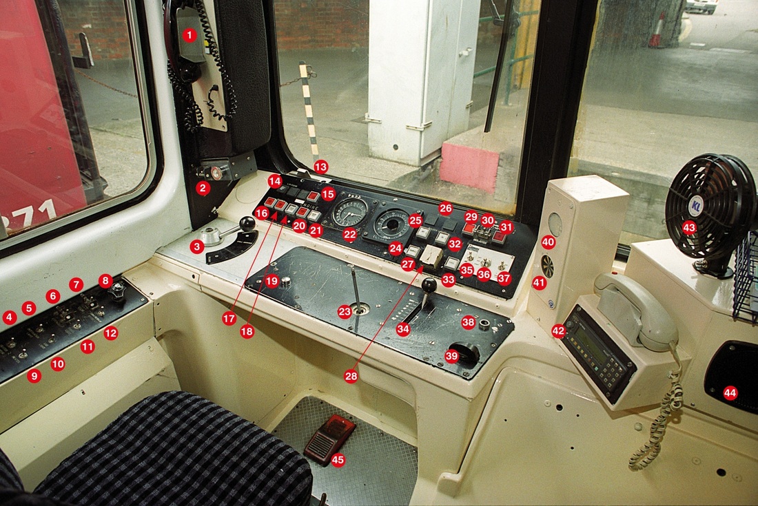
Class 143. 1: Cab to cab telephone and public address, 2: Drivers reminder appliance, 3: Brake controller, 4: Heater motor switch, 5: Destination indicator light switch, 6: Traction interlock switch. 7: Track circuit actuator isolation switch, 8: Windscreen wash/wipe control switch, 9: Heater switch, 10: Cab light switch, 11: Panel light switch, 12: Compressor speed up switch, 13: Emergency by-pass switch, 14: Position of original left side door open buttons, 15: Engine running light, 16: Gearbox warning light (train), 17: Gearbox warning light (local), 18: Engine start button, 19: AWS reset button, 20: Engine stop button, 21; Engine test button, 22: Main reservoir and brake cylinder pressure gauge, 23: Warning horn valve, 24: Speedometer, 25: Saloon lights off button, 26: Position of original right side door open buttons, 27: Couple button, 28: Uncouple button, 29: Fire alarm (local), 30: Fire alarm isolate, 31: Fire alarm (train), 32: Saloon lights on button, 33: Signal button, 34: Main power controller, 35: Tail light switch, 36: Headlight switch, 37: Marker light switch, 38: Master key socket, 39: Master switch (forward, neutral, reverse), 40: AWS alarm, 41: AWS indicator, 42: Cab radio, 43: Cab fan, 44: Loudspeaker.
|
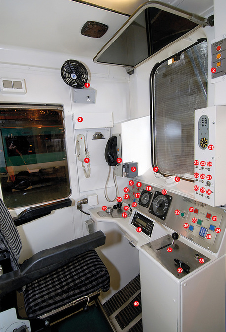
Class 150/1 driving cab. 1: Cab air fan, 2: TPWS system, 3: Lamp for illuminating notice board, 4: Radio telephone handset, 5: Driver-guard and public address telephone, 6: Drivers reminder appliance, 7: Emergency bypass switch, 8: Cab air vent, 9: Left side door open buttons, 10: Gearbox fault unit warning light, 11: Gearbox fault train warning light, 12:. Engine stop button, 13: Engine start button, 14: Windscreen wiper control valve, 15: Brake controller, 16: Horn valve, 17: AWS re-set button, 18: Cab radio, 19: Main reservoir and brake pipe pressure gauge, 20: Speedometer, 21: AWS indicator and alarm, 22: Marker light switch,
23: Instrument light switch, 24: Demister switch, 25: Destination indicator light switch, 26: Tail light switch, 27: Headlight switch, 28: Spare, 29: Compressor speed up switch, 30: Hold gear switch. 31: Right side door open buttons, 32: Sander button, 33: Driver-guard signal button, 34: Spare, 35: Couple button, 36: Uncouple button (below hinged flap), 37: power controller/throttle, 38: Master key socket, 39: Master switch forward, neutral, reverse), 40: Drivers safety device peddle. |
|
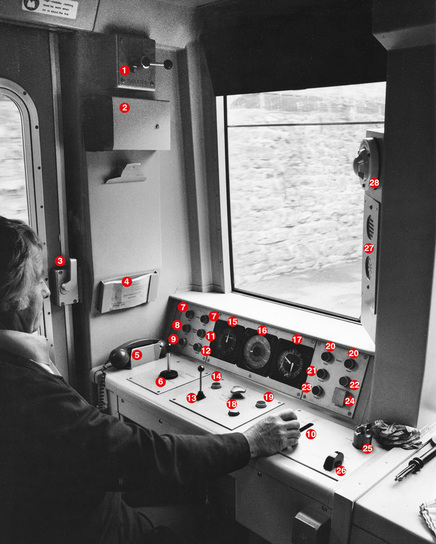
Class 151 driving cab layout. 1: AWS isolation switch, 2: Notice board light, 3: Manual handle for cab door, 4: Drivers fault/defect book, 5: Cab to cab and public address telephone handset, 6: Brake controller stalk, 7: Left side door open buttons, 8: Gearbox fault light unit, 9: Engine stop button, 10: Power controller/ throttle, 11: Gearbox fault light train, 12: Engine start button, 13: Horn valve, 14: Gear hold button, 15: Brake pipe pressure gauge, 16: Speedometer, 17: Main reservoir pressure and brake cylinder pressure gauge, 18: AWS reset button,
19: Compressor speed up button, 20: Right side door release buttons, 21: Signal button (cab-cab), 22: Spare, 23: Couple button, 24: Uncouple button (under hinged flap), 25: Master key socket, 26: Master switch, forward, neutral, reverse, 27: AWS indicator and alarm, 28: Cab air vent. KRD |
Above & Below Class 153 driving cab layout, above original or standard cab and below is the new or small cab. 1: Main reservoir pipe gauge, 2: Speedometer, 3: Brake cylinder pressure gauge, 4: Door interlock light, 5: Signal button (cab-cab), 6: Heated screen switch, 7: Cab heat fan switch (fast-slow), 8: Cab light switch, 9: Instrument light switch, 10: Compressor speed up switch, 11: Gearbox fault light unit, 12: Gearbox fault light train, 13: Headlight switch (day-off-night), 14: Tail/marker light switch, 15: Destination indicator switch, 16: Left side door close button, 17/18: Left side door open buttons, 19: Fire release override button, 20: Engine start button, 21: Engine stop button, 22: Couple button, 23: Uncouple button (under hinged cover), 24/25: Right side door open buttons, 26: Right side door close button, 27: Vehicle systems warning light, 28: Windscreen wiper valve, 29: Brake controller, 30: AWS re-set button, 31: Horn valve, 32: Power controller/throttle, 33: Drivers Safety Device (DSD) peddle, 34: Position for radio, 35: Master key switch, 36: Master switch, forward, neutral, reverse, 37: Emergency bypass switch, 38: Telephone handset, 39: cab-cab and public address handset.
Class 153 large cab fitted with radio and DRA.
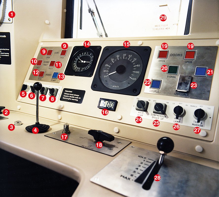
Class 155. 1: Cab to cab and public address telephone and call buttons, 2: Windscreen wiper controller, 3: AWS reset button, 4: Horn valve, 5: Cab heater fan control,
6: Windscreen heater switch, 7: Cab light switch, 8: Instrument light switch, 9: Left side doors open, 10: Gearbox fault unit, 11: Gearbox fault train, 12: Engine stop button, 13: Engine start button, 14: Main reservoir and brake cylinder pressure gauge, 15: Speedometer, 16: Clock, 17: Master key socket, 18: Master switch, 19: Right side door open buttons, 20: Signal button, 21: Spare, 22: Couple button, 23: Uncouple button (under flap), 24: Hold gear switch, 25: Compressor speed up switch, 26: Headlight switch, 27: Marker/tail light switch, 28: Power controller/throttle. Cab illustrated from set No. 155302.
6: Windscreen heater switch, 7: Cab light switch, 8: Instrument light switch, 9: Left side doors open, 10: Gearbox fault unit, 11: Gearbox fault train, 12: Engine stop button, 13: Engine start button, 14: Main reservoir and brake cylinder pressure gauge, 15: Speedometer, 16: Clock, 17: Master key socket, 18: Master switch, 19: Right side door open buttons, 20: Signal button, 21: Spare, 22: Couple button, 23: Uncouple button (under flap), 24: Hold gear switch, 25: Compressor speed up switch, 26: Headlight switch, 27: Marker/tail light switch, 28: Power controller/throttle. Cab illustrated from set No. 155302.
|
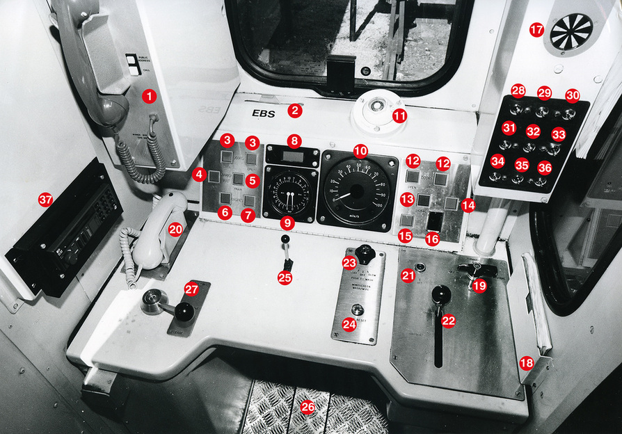
Class 156 driving cab. 1: Cab-cab telephone and public address system, 2: Emergency by-pass switch (EBS), 3: Left side door release buttons, 4: Gearbox fault - unit, 5: Gearbox fault - train, 6: Engine stop button, 7: Engine start button, 8: Clock, 9: Main reservoir and bogie brake cylinder pressure gauge, 10: Speedometer, 11: Cab ventilator, 12: Right side door release buttons, 13: Signal button, 14: Spare, 15: Couple button, 16: Uncouple button (under hinged flap), 17: AWS indicator with alarm above, 18: Driver's fault reporting book, 19: Master switch, 20: Radio telephone hand set, 21: Master key socket, 22: Power controller/throttle, 23: Windscreen wiper valve, 24: AWS re-set button, 25: Horn valve, 26: Drivers safety device peddle, 27: Brake controller. 28: Fault light dimmer, 29: Instrument light switch, 30: Windscreen demist switch, 31: Destination light switch, 32: Tail light switch, 33: Headlight switch, 34: Marker light switch, 35: Compressor speed up switch, 36: Hold gear switch, 37: Cab radio.
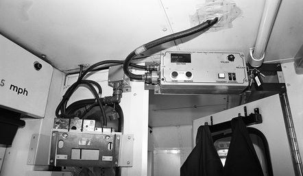
Left: RETB equipment. |
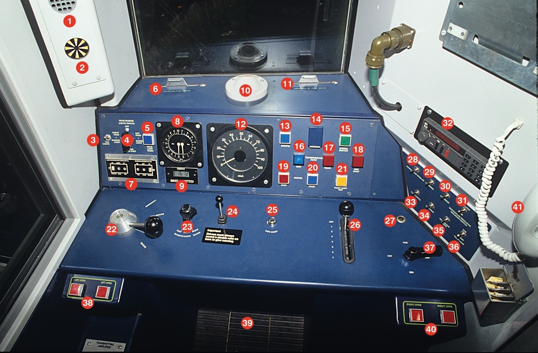
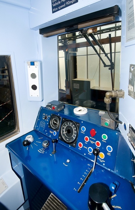
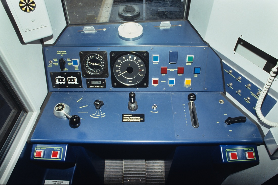
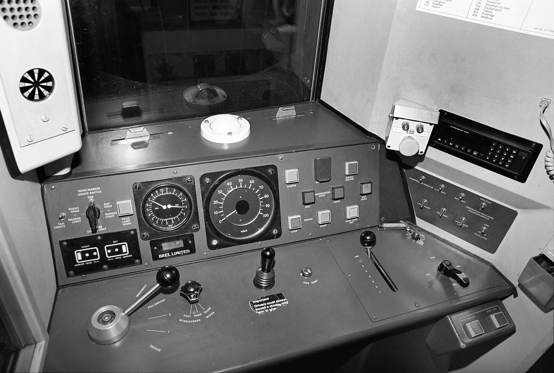
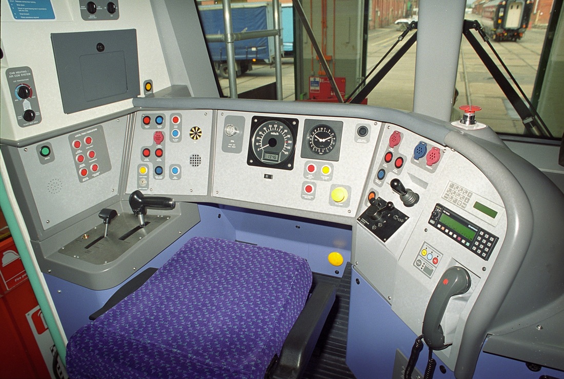
Original Class 158 driving cab layout, unit No. 158705original layout. 1: AWS indicator buzzer, 2: Automatic Warning System (AWS) sunflower indicator, 3: Tail light switch, 4: Head and marker light switch, 5: Headlamp warning light, 6: Automatic Warning System isolating switch, 7: Head/marker/tail light indicator, 8: Main reservoir and brake cylinder pressure gauge, 9: Clock, 10: Cab ventilator, 12: Speedometer, 13: Couple button, 14: Uncouple button (behind hinged flap), 15: Signal button, 16: Transmission fault - unit, 17: Transmission fault - train, 18: WSP fault, 19: Engine stop button, 20: Engine start button, 21; Fault lamp test, 22: Brake controller, 23: Windscreen wiper valve, 24: Warning horn, 25: AWS reset button, 26: Power controller, 27: Master key socket, 28: Compressor speed up switch, 29/30: De-mist switches, 31: Destination indicator isolating switch, 32: Radio, 33/34: Cab light switches, 35: Instrament light switch, 36: Bright/dim fault light, 37: Master switch, 38: Left side doors release, 39: DSD pedal, 40: Right side doors release, 41: Telephone hand set.
158 Wales & West with one-shot sander.
|
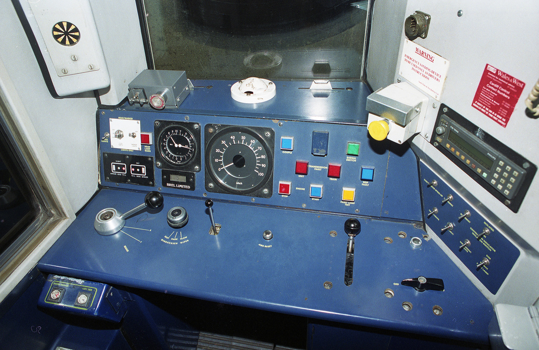
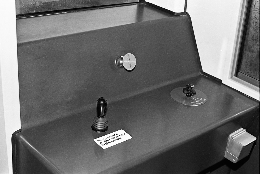
Right: Class 159, original cab design, fitted with 'one-shot' sander (left of radio). |
Above: Class 159 in as built condition.
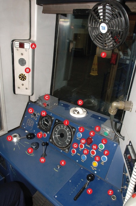
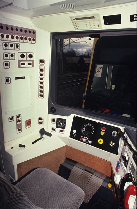
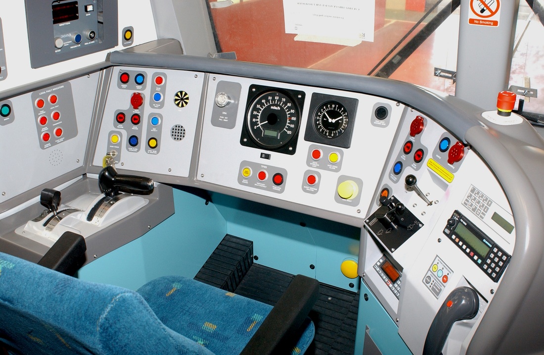
Left: Class 159. Class 159 refurbished cab layout from unit 159102. A: Door release light, B: Automatic Warning System (AWS) sunflower indicator, C: Drivers Reminder Appliance (DRA), D: Cab ventilator, E: One shot sander button, F: Cab fan, G: Headlight, marker light and tail light control switch with indicator below, H: Main reservoir and brake cylinder pressure gauge, I: Speedometer, J: Couple button, K: Uncouple button (behind hinged flap), L: Signal button, M: Transmission fault - unit, N: Transmission fault - train, P: Wheelslip protection, Q: Engine stop button, R: Engine start button, S: Fault lamp test button, T: Safety systems isolated indicator, U: Brake controller, V: Windscreen wiper control switch, W: Warning horn valve, X: Automatic Warning System, (AWS) reset button, Y: Power controller, Z: Master key switch Above: Class 159 non-driving side.
|
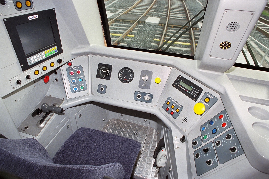
Class 168/0 fitted with Chiltern route Automatic Train Protection.
Class 170/4. As built condition.
Class 170/2 fitted with RETB and TPWS. 170270.
Class 175.
Class 180 FGW as delivered.
Class 185 'Desiro'.
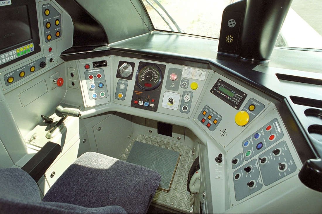
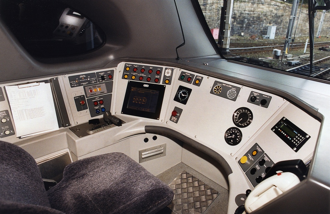
Class 220 Voyager - as built.
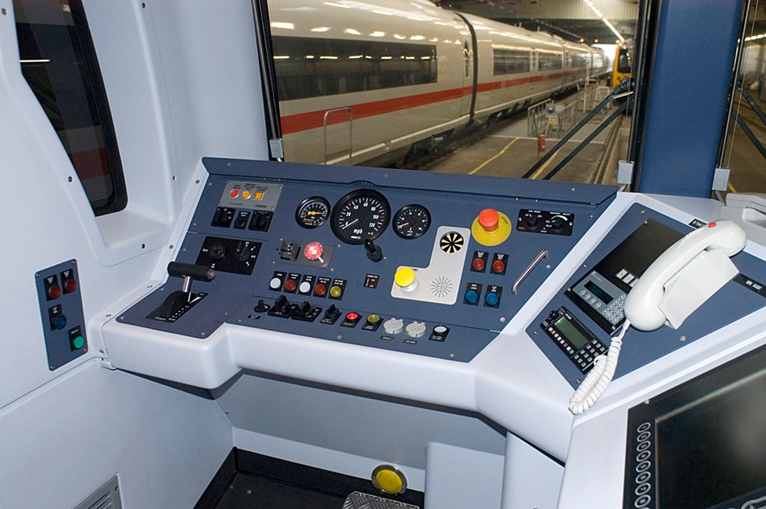
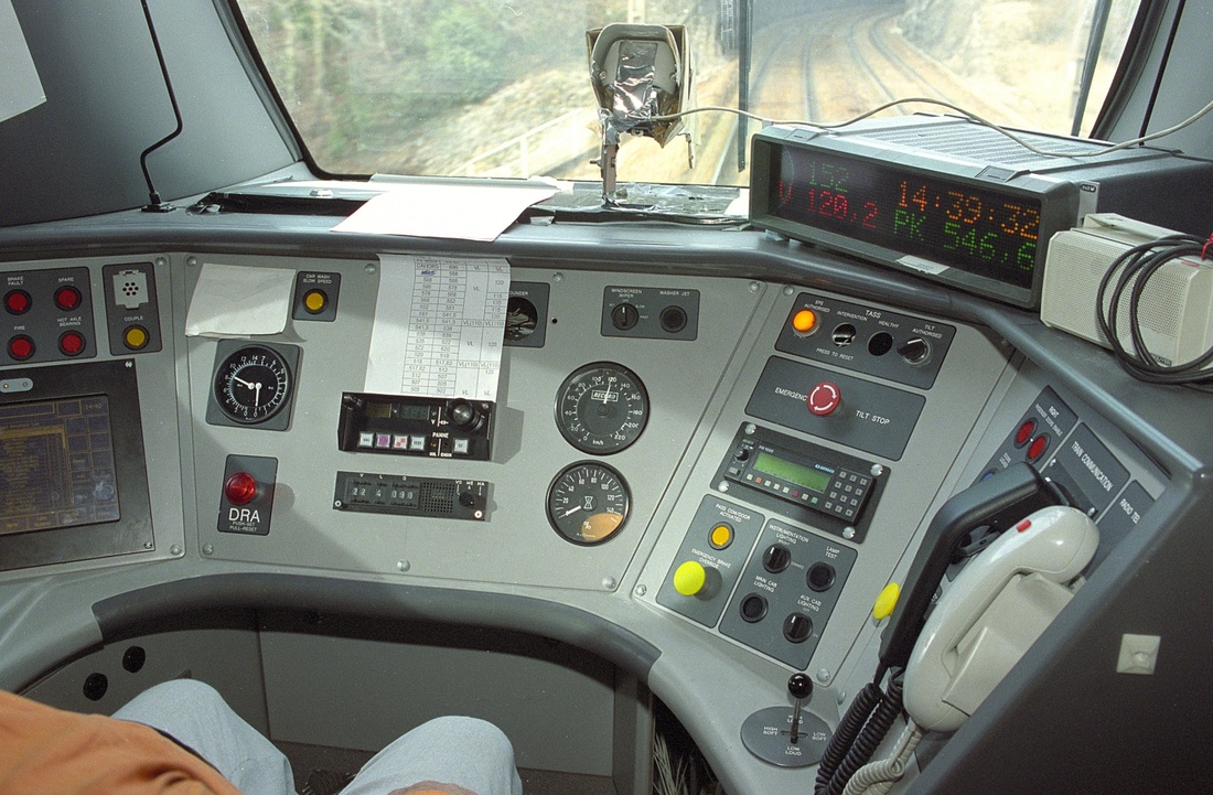
Class 221 as delivered.
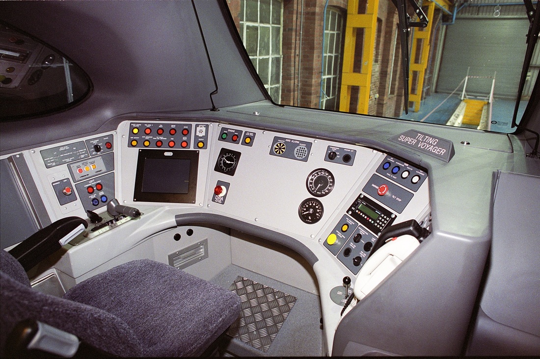
Class 221 'Super Voyager No. 221101 equipped to operate with French cab-signalling during trial running in France.
